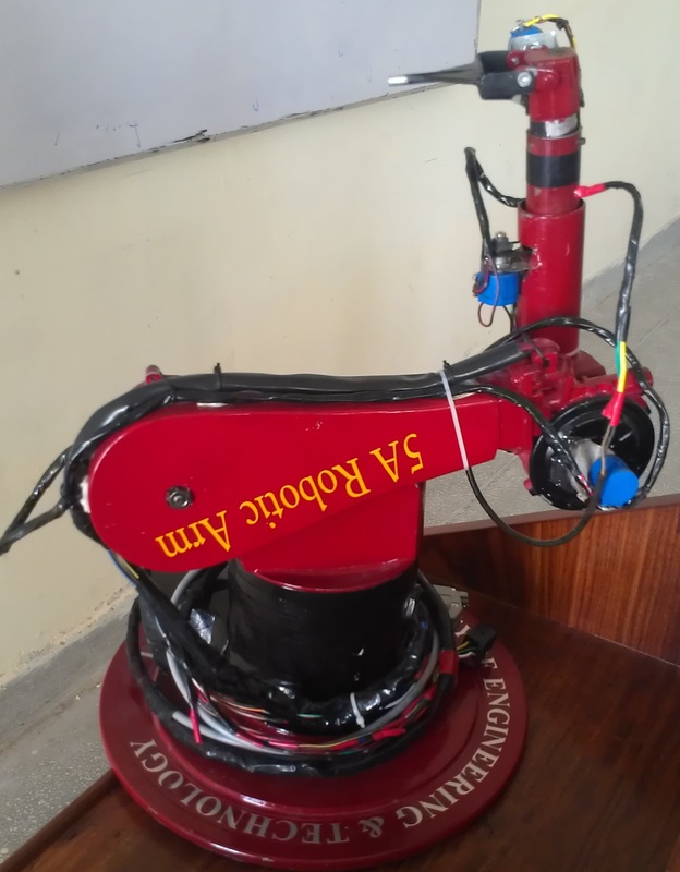
The configuration selected for this project is the revolute type that closely resembles the human arm. The arm's rotating base is powered by a single geared Dc motor that rotates the rest of the arm in a circle of 270 degrees. Mounted to the base is an elevation joint, or shoulder, that can move the arm through 140 degrees, from horizontal to vertical on each side. The shoulder uses one large scale Dc gear type motor to provide the torque needed to lift the rest of the arm, as well as any object that it may be grasping. Attached to the shoulder piece is an elbow that can move through 180 degrees, also powered by two Dc gear motors giving two joints.one joint rotates from 0 to 180 degrees and other from 0 to 280 degrees. The wrist is made up of one dc gear motor and can move through 100 degrees, rotating the gripper upward and down. |
|

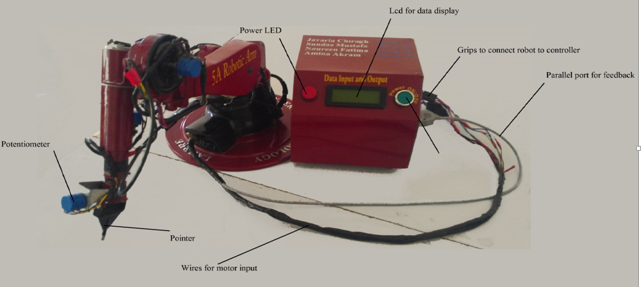
French potentiometers are used to provide feedback to microcontroller. PIC18F452 is used as Microcontroller to control joint motions. The Input is fetched from the position sensors, which tells the exact position of the robot and errors, if any. The controller then taking the position and errors into account makes the appropriate change in direction and outputs to motors. In this way the manipulator completes the required objectives.
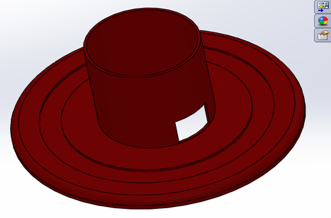
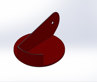
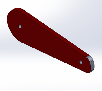
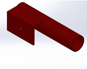
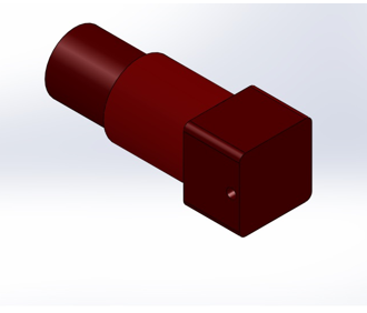
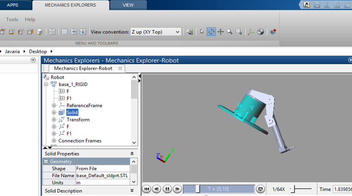
Forward Kinematics is evaluated using DH parameters. Peter Corke’s Robotic Toolbox is used to calculate inverse kinematics of robotic Arm. Robot’s Model is designed in Solid works. Each link is designed separately and then connected by joints.
Forward Kinematics is evaluated using DH parameters. Peter Corke’s Robotic Toolbox is used to calculate inverse kinematics of robotic Arm. Robot’s Model is designed in Solid works. Each link is designed separately and then connected by joints.
|
|
|
|
|
|
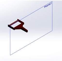
Our manipulator is 5 DOF so we designed 4 links connected by 5 joints. Simulation of robot model is done im MATLAB & Simulink. For this purpose a preconfigured robot.xml file is generated by exporting robot model and this CAD file is imported into Simulink.
Robot is attached with Motor input wire and potentiometer feedback wire coming from its controller housing. Both are to be attached with controller housing. Usb-Rs232 CH341 cable for serial port connection is attached to computer for control. Reset button is there to reset the controller in case the system is hang up at some time. Power On/Off button is on the back side of Controller housing.
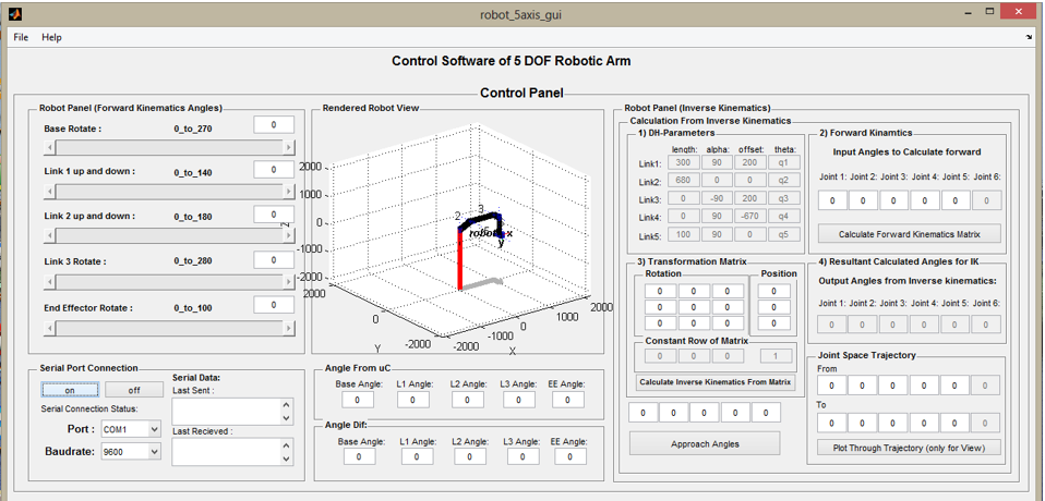
Software for control of Robotic arm is designed in MATLAB Guide. Software has Forward kinematics panel, having 5 sliders, one slider for each
joint. By moving any slider we can change the position of any joint. Joint
restrictions are given for each joint in slider max and min positions. Slider
callback sends angle change command to serial port. Serial port block which contains serial data sent and received text boxes, list of available communication ports to be connected , buad rate selection list box and serial communication On and Off buttons. Inverse kinematics panel in which DH-Parameters of robot are shown that can be edited from
code. Forward kinematics for any posture of robot can be calculated.
Transformation matrix can be seen and edited. By giving transformation matrix
values inverse kinematics of robot can be found and approached. Trajectory plotting panel is to view joint space trajectory in rendered robot view.
Initial position and final position is entered in the edit boxes. Plot of robot posture is shown in the figure in the
software.